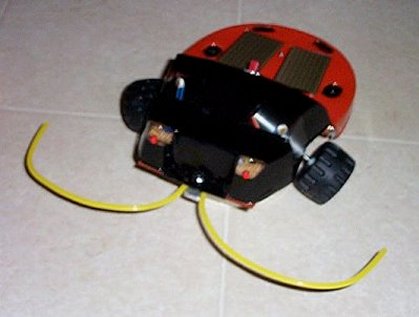
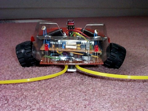
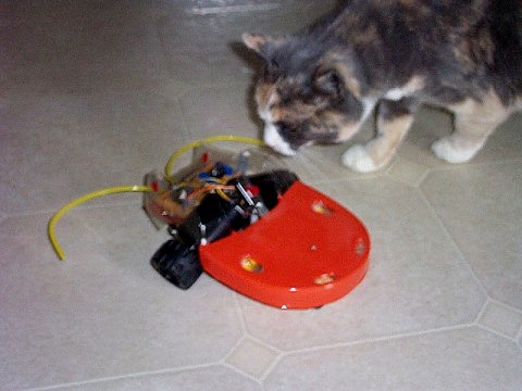
The almost finished critter. Solar cells are not hooked up yet.
Yes, thanks, I noticed the bent over LDR.....
The almost finished critter. Solar cells are not hooked up yet.
Yes, thanks, I noticed the bent over LDR.....
WHAT IT IS - An environmentally aware "virtually alive" photovore robot bug following the BEAM philosophy. It walks (well, rolls for now), talks - (chirps in response to light level), sees - (photo resistors sense brightness to guide it), feels - (via touch sensing feelers of course!), feeds - (coming soon via solar cells charging rechargeable batteries - once enough light is located, bot will go to "sleep" to recharge).HOW IT WORKS - A stacked pair of 74ACT139 ICs control two Hankscraft gear motors from pulsed signals from a dual 556 timer IC. This "brain", based on Craig Maynard's Cybug's 555 design can be studied on his "Cybug brains" site at:
http://members.home.net/cybug/Cybugs/brains1.htm
Simply put, the motor on the side with less light runs faster causing the bug to turn toward the lighter side thus eventually locating the brightest area in it's environment.
As for obstacle avoidance, the bug's feelers send a signal to the motor drivers and reverse the opposite motor turning the bot away from the obstruction. Since the obstruction side motor continues to run forward, the bug turns on a spot for a time set by a timing capacitor. The present value gives 180 degrees more or less in about one second with the LDR trimmers set to low motor off time.
If both feelers contact at or near the same time, both motors run in reverse for the timer value. It's rare that they would touch at exactly the same time so in effect there is almost always some turn away action so that it won't just sit in one spot repeatedly ramming a wall for example. It's been tested under a dining table with chairs in place and it will eventually find it's way out. Only once did it get hung up when it's oversized feeler hooked a leg when reversing and had too many other chair legs in the way to free itself.
The motor driver is based on the Z-bridge design by A.A. van Zoelen - "A Cheaper H-Bridge Design - the Zoelen Bridge (Z-Bridge)" can be found at:
http://www.serve.com/heretics/BEAM_Tek/motors.html
Being this is my first robot, I'm very happy with the design so far and already have ideas for expansion. It's modular "breadboard-like" layout will allow easy modifications and additions.
The body is from the cover of a stereo headphone package, trimmed and painted with acrylic on the inside to give it that gloss coat look. Everything else for the frame was spare parts or junk I had laying around. A strip of aluminum, a couple sticks, some small angle brackets, nuts and bolts, and perf-board for the circuits. Toy wheels with some snug fitting nylon spacers fit right on the motor shafts.
As everyone is designing smaller and smaller BEAM bots, I elected for big and bad! With the trimmers adjusted for low off time, It travels up to 6 inches a second in the dark, (The motors turn at about 30 RPM) it has plenty of room for bells and whistles, and scares the hell out of our cat! I swear it follows it around the room. I've never laughed so hard as when the bot got into a grocery bag laying on the floor and the cat attacked it! I guess she thought she had it cornered at last. Every time the bot would start to find it's way back out of the bag, the cat would grab at the feelers and the bot would spin around and go back inside. This made the cat even madder and....well, you get the idea. Nothing but fun in our house!
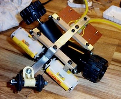
Construction is straight forward. Tail wheel is spacers with grommets.
Caster is unknown part I had for years. Knew I'd need it eventually!
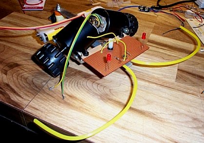
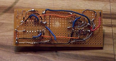
This circuit board will hold the options and feeler contacts.
Feelers are RC plane control rod inserts. Wheels from toy.
This board stacks on top and is the brains.
The body is just a headphone packaging cover, trimmed to fit.
Wish I'd planned it a little better, ended up with way too many wires to deal with.
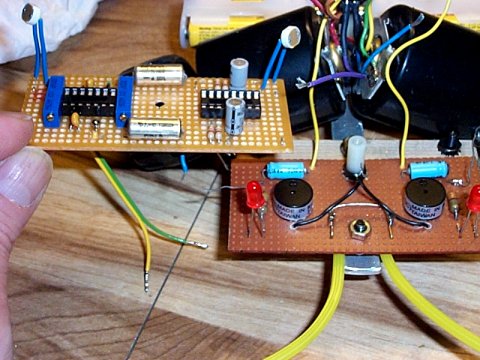
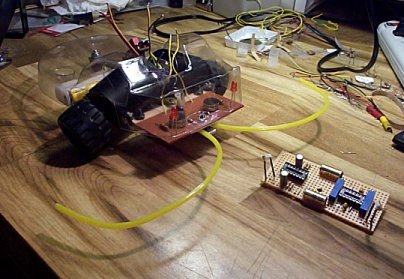
How they stack up. At least the tops of the boards look neat :)
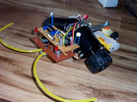
Finally complete. On/off switch is temporary of course for testing purposes.
We mean business!
Test run with a partially painted body fooled this critter...
Final paint and hatch cover around switch.
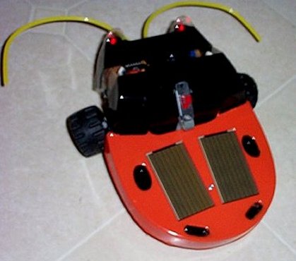
Windows left clear for LEDs and LDRs.
Solar cells just put on with double-sided tape for this picture.
Here's the schematic for the Rug-Bug.
Notes: If you build one for yourself, be sure to experiment with the LDR sensitivity trimmers.
It was two days before I realized that if I turned them way up from the 330 ohm bench test settings, that the off time of the motors
would allow the bot to waggle around much more realistically than when the motors both run almost constantly.
The phototropic sensitivity is such that the bot will literally circle a desk lamp sitting on the floor.
Experiment with it. You will be impressed with it's behavior!Below is the logic usage of the 74ACT139 motor control in case you are interested.
Note that inputs A1 are the pulsed signal from the 556. A high through the feelers to either
A0 input reverses that motor thus the feeler needs to be on the opposite side of the motor
it will reverse to turn away from an obstacle.
(c) 2000 - 2007 Ace Sim RC - Medford Oregon USA - All rights reserved.