The
Laymens Guide To
Virtual
Reality Motion
Flight
Simulators
Copyright © 1997 - 2023 Ken Hill
CHAPTER TWO - THE MOTION PLATFORM
WHY A MOTION PLATFORM
The first time you dodge some incoming triple A fire and darn near fall off your office chair, you'll see the need for a motion platform.
Once you attempt your first carrier landing in a moving platform and experience the adrenaline rush of excitement, and a load of other emotions that give you the famed "pucker factor" of real flight, you'll realize that you've now found the missing link to pure immersion flight simulation.
OK, it's big, bulky, ugly and hard to get into. But being able to fool your mind into thinking you're really doing those snap rolls makes it all worth it. After all you've always wanted your own personal 'ride' ever since you were a kid, right?
If
you only want beauty, set up a static replica cockpit with blinky lights, slick
decals and such and impress your friends with your good taste. "STIMBOX"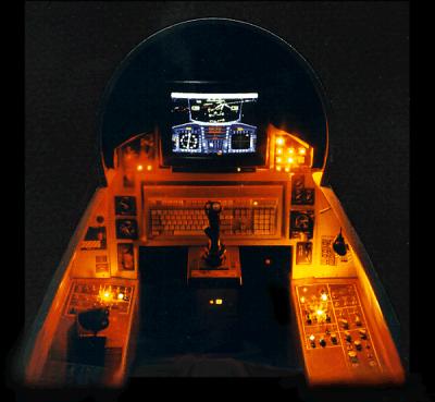
For
the real flight experience, turn out the lights, hop into a JoyRider, crank up
the volume, and let the vertigo begin.
"JOYRIDER"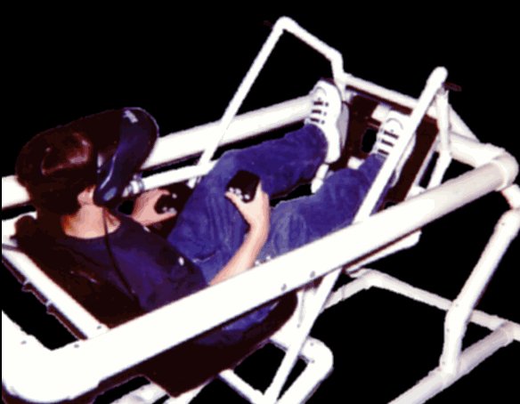
DESIGN CONSIDERATIONS - HOW IT WORKS
Based on a balanced gimbal system along the center of gravity axis for pitch and roll, the JoyRider suspends the pilot and cockpit high enough to clear the stand, and allow enough room for the ranges of motion.
You may be saying; "Hey I already have an office chair that tilts forward and backward and have even mounted my joystick and throttle to the arms so it all moves together. It even rotates for yaw. Can't I just make it rock side to side and not have it be so big?"
Yes
you can but not without lots of design problems. What you would be trying to do
is put your mass OVER a pivot. This makes you want to tip over. That's why
office chairs have that big spring underneath. To make this type of design you
need to add a floor with heavy counterweights to balance the pilots
top-heaviness. See "FLYIT"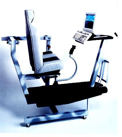 for this type
of platform, and even it has it's pivots above the base.
for this type
of platform, and even it has it's pivots above the base.
More weight increases mass so to have a responsive platform, one must design it as light as possible. To support the human body plus any additional hardware requires certain structural considerations. Learning from aircraft design which requires light weight and strength, one could come up with a molded composite structure, but this isn't simple or inexpensive for the homebuilder, nor can it be easily torn down to a reasonable size for transport or storage.
MATERIALS
PVC CONSTRUCTION
Our prototype is made of PVC pipe that's relativity light, cheap and available. Fittings are numerous so little custom fabrication is required. To easily make design changes, we used screws and bolts to hold it all together. A finalized design could be glued except for disassembly points and would look a little cleaner. For strength only use schedule 40 thickness tubing in large enough diameters that will support the required weight.
WOOD CONSTRUCTION
If you are a woodworker, you may wish to make your platform out of wood. We toyed with this idea but realized that to adjust the design we'd have to remake a lot of parts. Try to use box structures where possible for weight reduction, and think adjustable and expandable in your design.
METAL CONSTRUCTION
Metalworkers may choose steel or aluminum. Use thin wall tubing if steel, and choose large enough diameters that won't deflect much when you get excited and start bouncing around in the seat. A little flex adds to the excitement however!
COMPONENTS- Minimum
Requirements
COCKPIT- You should design it from the inside out. Start with a seat, aluminum lawn chair, go-cart, PVC yard chair, etc. Think LIGHT and WIDE! You want enough room between your legs for control stick movement range.
Figure out appropriate attach points for the seat frame side rails. The rails must support your weight from the pitch pivot points without much deflection. Remember that not only must the rails support your weight downward but also at the different angles of motion. To test material strength, place both rails between saw horses at the seat attach points and put all your weight at the estimated distance for the pitch pivot point. You can generally figure that the human body's center of gravity (CG) is about at the navel if viewed from the side. The seat frame should at least be attached to the seat in four places and have a footrest.
GIMBAL FRAME- The gimbal frame consists of a rectangular frame, outside of the
cockpit frame that attaches to it at the pitch pivot points. It also connects
to the base at the roll pivot points. Leave enough room on the inside for the
bearings (see hardware below) to be attached to the outside of the cockpit.
To test your choice of materials for strength, support the ends of one of the long members on sawhorses and put all your weight in the middle. Some flex is OK since you will be dividing the load between two lengths. Remember that in reality the gimbal frame must support the entire cockpit, all its accessories like throttle, rudder pedals, display, etc. PLUS yourself.
BASE-
Possible layouts depending on materials and tools.
To test your base
design for strength, put all your weight on one end post or end panel with the
base flat on the floor and unsupported. There should be no flex or play in any
direction.
HARDWARE-
Ball bearing pivots are highly recommended but metal bushings could work if
designed right. We used heavy duty caster bearings by removing the wheels and
opening the forks in a vice. NOTE - Only get casters that have a torsion race
for this use. Since you will be using them vertically instead of horizontally
as they were designed, the extra torsion bearing race takes the twisting load
you'll be applying. Do NOT even TRY the single race type. They'll wear out
overnight!
The correct type to find have the normal bearings sandwiched between the mounting flange and the wheel fork bracket plus a second race between the wheel fork bracket and another plate on the wheel side of the bracket. Just look up under the wheel. If you only see a rivet, then don't get it. The type you need has what looks like a large, fat washer under the rivet that's slightly concaved. You can't see them, but the second set of bearings are in there.
The trick setup would be to attach bearing races into the gimbal and cockpit frames and use jack shaft type roller or ball bearings specifically designed for this type of loading. Much more spendy and complicated, and really not necessary as we've logged hundreds of hours on our JoyRider with the above described type of caster bearings with no noticeable wear. Just be sure to get the correct kind!
MOTION
LIMITS- The cockpit
will only be able to move side-to-side as far as you have room between your
legs for the stick to move. Forward and back stick movement should be limited
with mechanical stops on the cockpit frame to gimbal frame. Don't try to place
limits on the stick as the leverage can get great enough to bend it under the
right conditions.
The down stop is needed for the cockpit when it is unoccupied as most of it's weight is forward when empty. The up stop is needed so that at full aft stick, it doesn't hit the seat front (or worse if you have a really short seat!) We accomplished both needs by putting a foam padded U shaped bar around the outside of the gimbal frame sides and connected them to the cockpit frame.
CONTROLS- If you are an electronics, hydraulics,
and or pneumatic engineer and have access to parts, by all means consider a
powered platform. Driver boards can be used to drive stepper motors or
hydraulics to move the cockpit from stick inputs just like the big boys.
For our cheap and easy passive platform however, we'll simply attach one end of the center stick to the cockpit, pivot the center of the stick on the stationary base frame, and move it all around by hand from the top of the stick.
Having a nicely balanced platform is a MUST as too much self centering causes excessive stick pressure. The location of the sticks pivot point and section length can be adjusted to supply some leverage to help this condition, but the space shortage between your legs limits how much you can get.
To compensate for the sticks offset forward from the center of the pitch axis, it's necessary to allow the sticks center pivot to change location relative to stick position. Simply put, the sticks center pivot support frame that connects it to the base needs to rock up and down slightly. Hinge or bearing it to the base frame at both sides. This support needs to be as solid as possible in side to side strength.
CONTROL STICK- Aluminum tubing is a minimum here as leverage bending loads are high. Use 7/8" .049 wall or better. Use aluminum or steel channel that fits the exterior of the tubing for fittings. You'll need one for the cockpit connection (stick bottom) and one for the center pivot (middle connection to base).
We oversized the brackets a bit to allow room for washers between the channel inside and tubing outside to prevent wear. Drill very precise holes to prevent binding and don't allow the bit to oval the holes. You want a slop free pivot that'll move freely but with no excess play in any direction. Bushings in the tubing will increase longevity as this seems to be the platforms weak link if using too thin a wall tubing.