Wally Wonder Wing V2 Construction
#6 FUSE POD
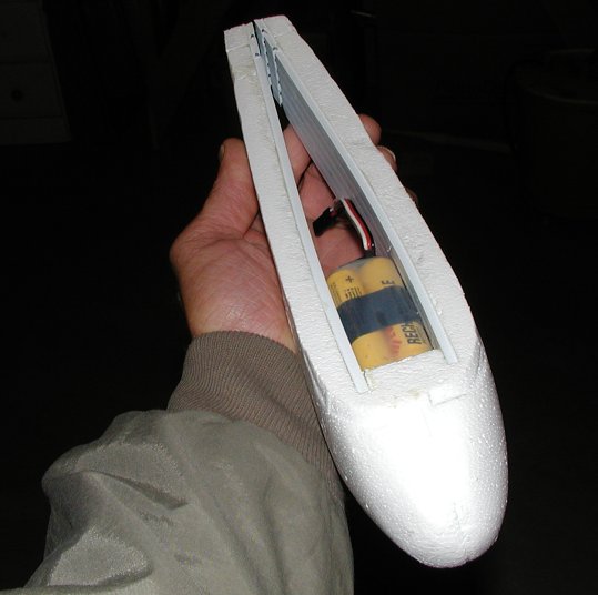
Fits 8) AA square brick packs or 8) 600 flat packs or any others that measure 1.25" square.
Needed:
Stock glider foam fuse
2) 9.25 inch long x 1.5 inch wide pieces of 1/8 inch thick coroplast/corex corrugated plastic sheet.
(get at craft store or sign shop)
2) 1/8 inch wide, double gripping nylon wire ties at least 6" long
4) thin bamboo skewers
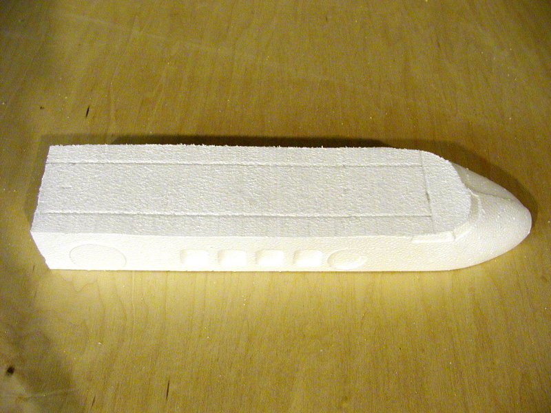
We'll use the stock fuse shaped as shown.
Cut off the nose right at the LE of the wing cutouts.

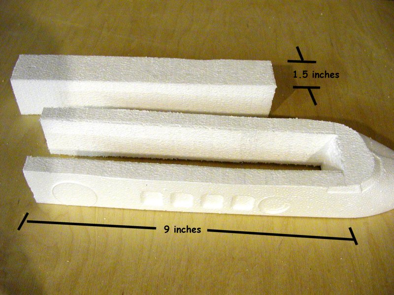
Measure out horizontal lines at 3/4" up from the bottom, and 1.5 inches up
from there.
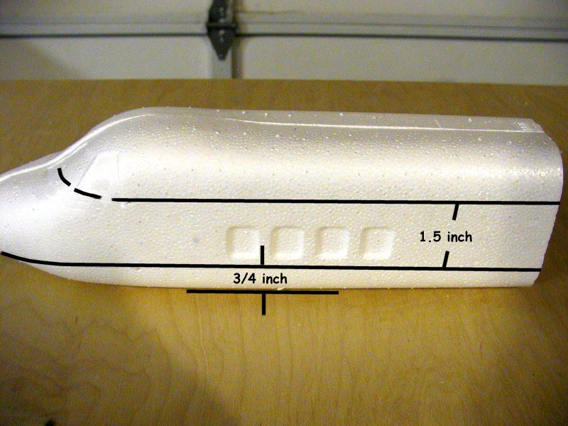
Like this.
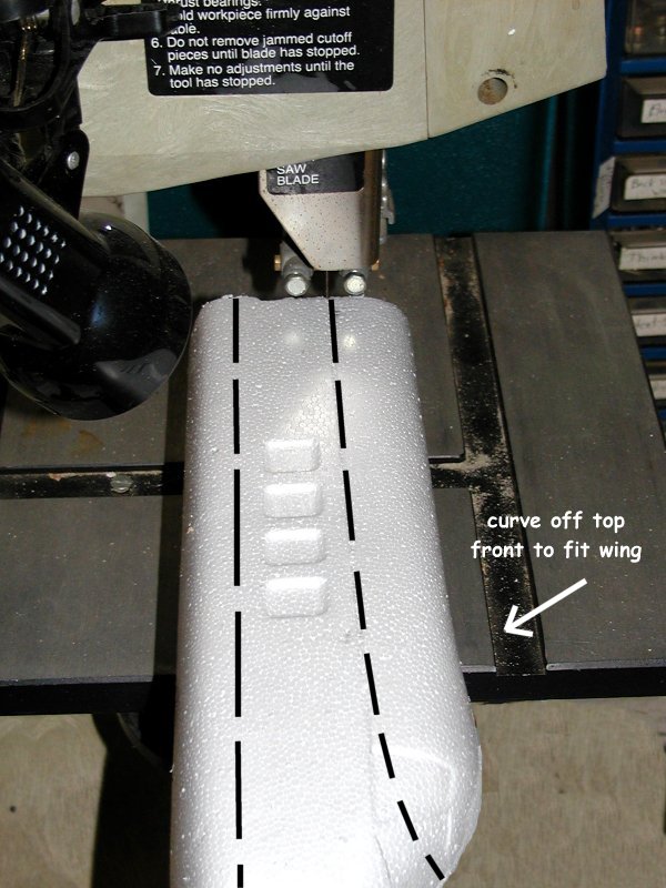
Cut straight through with a band saw, or other fine toothed saw from back
to front in both places.
For the upper cut, curve the cut up off the nose.
A hacksaw works good if a band saw isn't available.
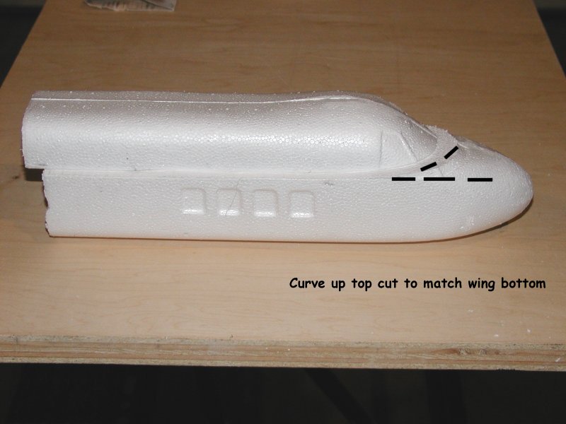
For the top cut, curve up at the front more than is shown here.
Ideally the top cut will match the wing's bottom. Leave some extra
and sand down to match.

Here's what we want. Slick eh?
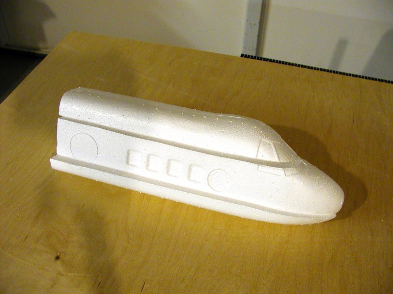
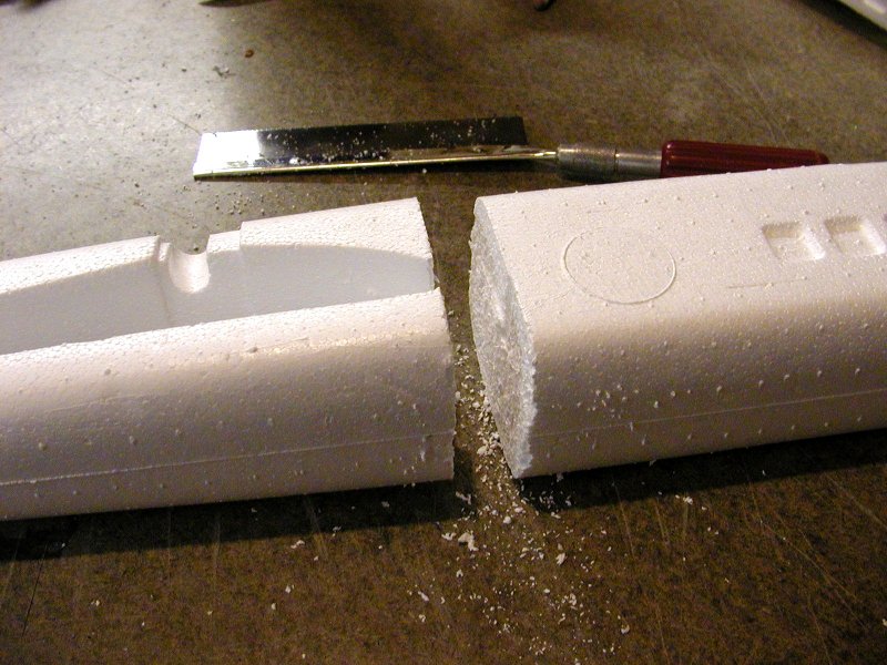
Slice & dice!
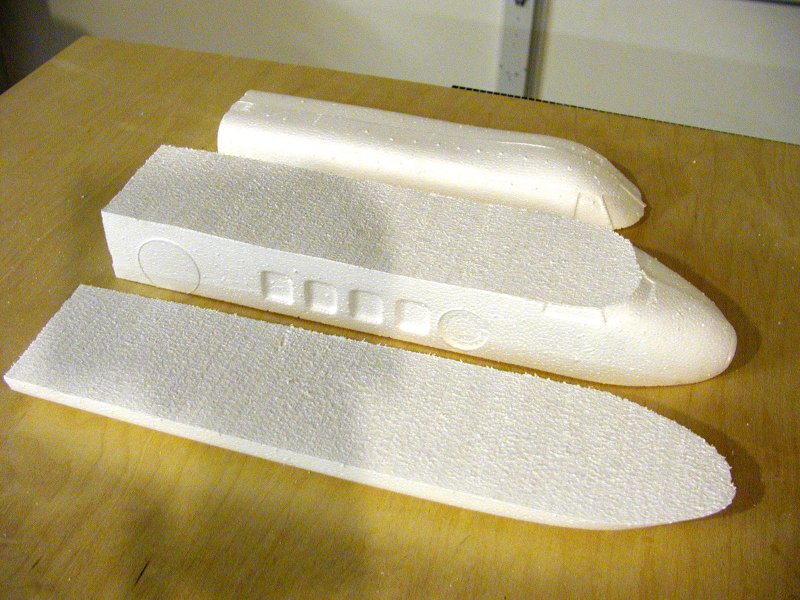
I found that carving out a fuse is a real pain without a hot-wire setup.
This way, it's no sweat and once epoxied back together the fuse is probably
stronger than the original.
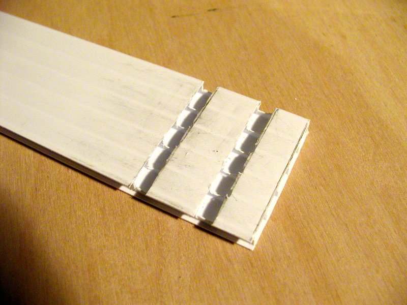
Measure out the center section 1.5 inches wide and 9 inches long.
(if using larger than 1.25" square packs, enlarge this dimension by the difference
in size)
Saw both sides up to the front mark and keep going another 1/4" further into
the nose.
Then use a knife to make the final cross cut.
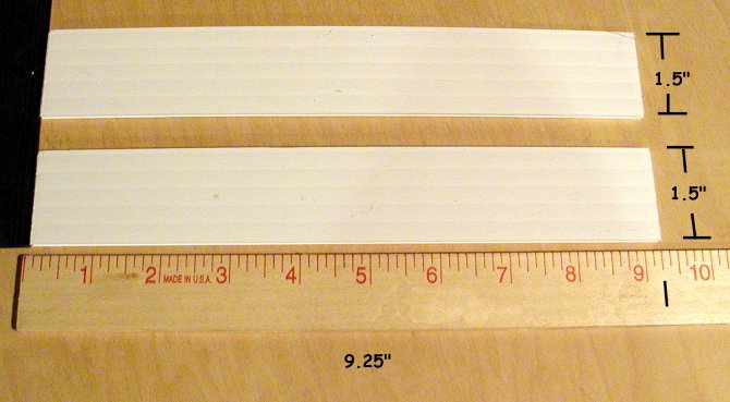
Cut 2 side walls from 1/8 inch thick Coroplast 9.25 inches long and 1.5 inches
wide.
Cut the top edge along a flute web for strength where the wing sits.
Be sure you have at least 5 segments intact (6 webs).
Mark the outsides (where you'll later glue) with an arrow for quick reference
to the tops.
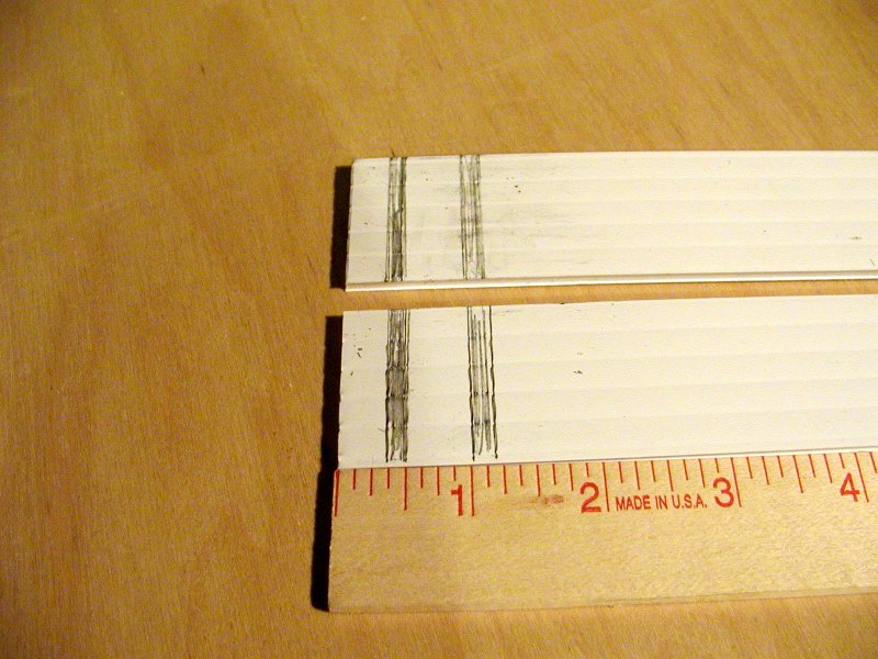
Measure and draw marks as shown on the inside rear of each wall.
Lay your motor in-between for reference.
Try to line up the forward mark with the motor case cutout.
This helps hold motor from moving forward from nose in.

Cut out marked area but only down close to bottom surface.
Like this.
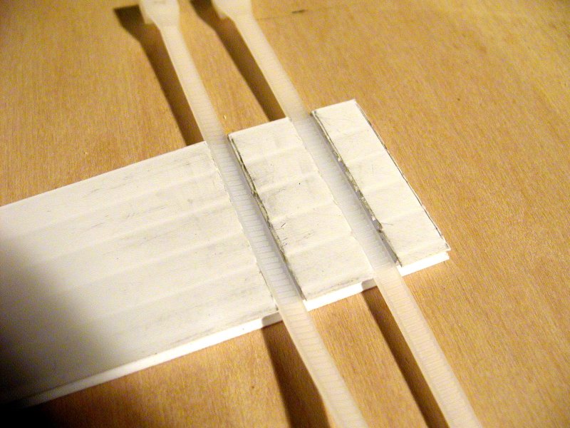
Lay in your ties to test fit.
(mine were 3/16" wide, but 1/8" is plenty if tight)
They should lay recessed on the bottom, not up much on the webs.

Add the skewers to hold in place. Does it get any cooler than this?
Remove for now and we'll glue the side walls in the fuse.

Rough sand the outsides where the glue goes.
Fit into fuse center and trim bottoms if needed for flush fit.
Note that the walls are 9.25" long but our main cut-out is only 9" deep.
Widen out the 1/4" long extra cut you made in the nose to 1/8" wide for the
excess side wall length to fit in.
The rear should end flush with the foam.
This adds strength to the nose by reducing the sheer line caused from the
cross cut.
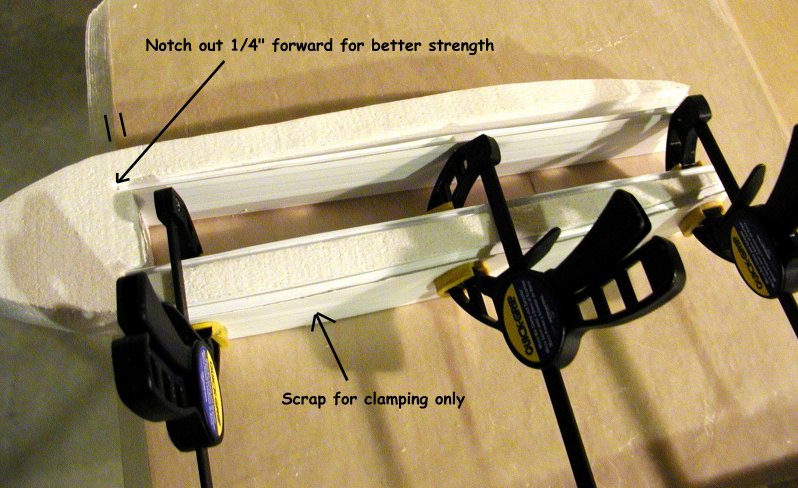
Epoxy each into fuse center section with motor mount slots to inside rear
and flat edges up.
Use a scrap of Coroplast under clamps on outside to prevent smashing the
foam when clamping.
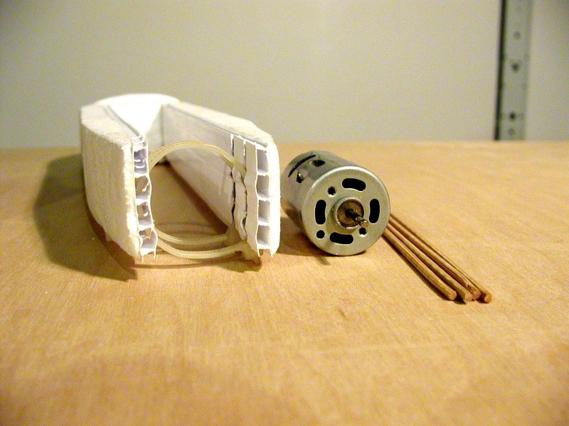
Fit wire ties into slots. Put latches up and stagger to sides.
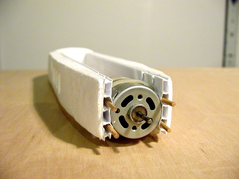
Insert the skewers as shown so motor is centered on the walls. (this one
is missing a flute on the bottom)
It should be laid out as follows: open web, skewer, open web, skewer, open
web.
The sticks could be cut shorter, but since they are so light, there's no
need and they might add some extra strength to the sidewalls.
Once ties are tight, they won't be going anywhere so no need to glue, just
push in flush before tightening ties.
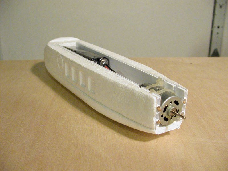
Epoxy on the bottom foam after fitting with battery pack and motor temporary
installed for width change.
Shape foam to a taper at the rear but don't get too thin.
For a sloper or HLG pod, just pinch the back of the sides together.
Have your receiver pack in place in the nose and mark the curve it makes
on the bottom before gluing.
After glue is set, you can cut and shape the bottom foam to match this contour
for a nice streamlined profile.

Plenty of room here.
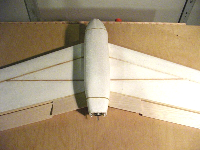
Note the lip on the front top cut fitted for the wing seating.
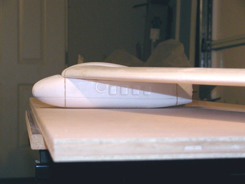
Pod is simply attached to the wing with rubber bands looped over the wing
and hooked under the front and rear of the pod.
We used this method at first temporarily during testing to have an easy way
to adjust the CG.
It worked so well that we're sticking with it!
You can always find some matching color rubber bands if you think it looks
too distasteful.
(use about 3 of them, or 2 if you'll really check them each flight!
We tried dowels inserted through the fuse sides for the bands, but abandoned
it after they starting getting loose from crash "testing".
The simple method shown above has the advantage of releasing the pod from
the wing without damage from any direction of impact.
Of course your nose will get wrinkled over time, but I hear that a heat gun
and mitt will take it out pretty good.
BACK TO INDEX
NEXT PAGE