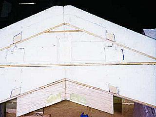
This is the beginning. The spars are 1/8 x ½ spruce. The foam is easily routed out for the spars with a dremel tool and an 1/8 bit. The trailing edge is 1 ½ TE stock. I originally planned on just making the Wally Wing so the ailerons are already cut out.
I cut a tip rib from 3/64 ply and glued it to the foam on each wing tip, connecting the main spar and TE cap. I did this because I planned on screwing in the tip plates with small wood screws. It also helps to tie the spar structure together for strength.
As construction progressed I contacted Ken with some questions I had. Ken is a very cool dude and was very helpful with all my questions. Considering how busy he is with all the projects he has going on it was greatly appreciated. At any rate somewhere in our correspondences I mentioned that I had seen his Polly on E-Zone and I was begging for more info because I wanted to build one. He mentioned that he had always thought the Wally Wing could start out as a trainer (i.e. a boom V-tail) and then be converted to an aileron trainer and finally into the original Wally Wing so the plane would progress with the skills of the pilot. Well I was hooked again so before I even finished the Wally Wing I just kept building it into the Polly Wally you see here.
Keeping with my mantra, cheap is best I rummaged around in the attic and found some aluminum/graphite arrows I had from my archery days and went down to the local hardware store for the nylon wire clamps etc. I stopped at my local sign company and bought a 4 x 8 piece of 3mm coroplast (corrugated plastic) which I used for the tail feathers. Once all the materials were assembled I took the phone off the hook, kissed the Mrs goodbye and descended into my hideaway, the basement, for some fun and adventure.
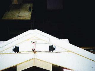
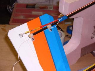
I decided to mount the arrow shafts at 8 apart. At that width they run just over the base of the servos in the wing and provide some added insurance that the servos wont go anywhere. I routed out four small areas in the wing up against the spars for my hardwood mounting blocks. The blocks were made of two pieces of 1/8 x ½ spruce laminated together. My first mistake was to laminate both pieces of hardwood with the grain running the same way. ALWAYS cross laminate small pieces. When I went to screw the shaft down to the wing my little hardwood mount split. A little epoxy and it was good to go but if it had been cross laminated it would have never split duh!
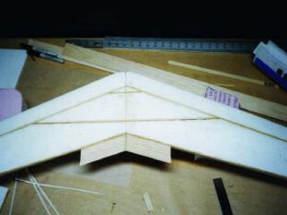
This pic shows the hardwood inserts to mount the arrow
shafts and the cut outs for servos and receiver. I routed out the underside
of the wing with my trusty dremel tool and a 1/8 router bit for the servos
and the receiver. Once cut out to fit snug I brushed on a thin coat of
epoxy to harden the pocket and add just a little more to the press fit.
I routed out two small channels from the servo bays to the center of the
wing where the receiver is mounted. This way everything is built in and
nothing protrudes.
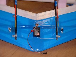
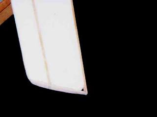
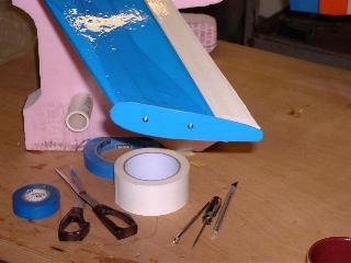
And heres how it looks after covering with packing tape!
The tail feathers are cut out of one piece of coroplast. I have just started working with coroplast and it is some great stuff to work with. It has a lot of flexibility and can be made to bend and flex wherever you want if you cut it right. Look on some of the RC forums for links to Spad to the bone or similar sites where working with coroplast is explained in detail. Suffice it to say the tail feathers came out perfect.They are mounted to the booms with 2 nylon wire clamps on each boom. I used a small sheet metal screw with a 5/8 square piece of 3/32 plywood as a wood nut on the opposite side. I was careful to tighten the screws until everything came into full contact with the plastic but was careful not to over tighten. The control horns are standard issue but again dont over tighten!
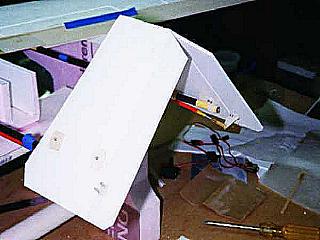
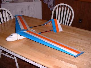
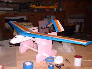
And heres what it looks like all prettied up.
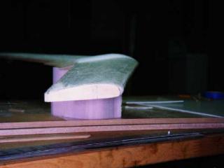
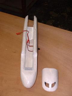
I really liked the new design of the pod that Ken
had created for the Polly so I bought another $7 glider and went to town
on the fuselage. Again, Ken explains it much better than I could so heres
a pic of the finished product. Youll notice that I cut out the two front
windows of the fuse top
.this will let plenty of air in to cool the battery
before exiting through the motor, and it looks cool.
After that it was a matter of covering the plane with packing tape. I had never attempted this before and I found out it takes a little practice but the end result is pretty darn nice. The fuse pod is rough because I only figured out how to wrap the tape around curved edges three quarters of the way through the job but from four feet it looks great. I used reinforcement tape on leading edge, the nose of the pod and several other high stress areas per Kens instructions.
I used a 7.4 volt speed 400 motor, a 6 x 3 plastic prop, a Sun 1000 ESC / BEC and a 600 MAH battery. The receiver and radio are the new Futaba AM 3 channel components and I went with the equivalent of HS 81 servos. All up weight ready to fly was 29 oz with 3 oz of lead in the nose due to the boom. Once balanced out I plan on replacing the lead with more battery for longer flights.
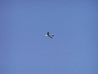
So far I have only glided the model, as the weather
here in Connecticut is windy and cold. Initial glides indicate she is going
to be a real flyer. With a little speed the glide is very shallow and as
Ken has described in his Polly article, walking out to retrieve her after
a test glide was a hike.
One might assume this is the end of the story but for me it has only just begun. Alternative material building is fun and challenging and I plan on cooking up some more foam and tape in the near future. I wholeheartedly encourage you, dear reader, to give it a try following Kens instructions. Its a hoot!!
Paul Des Biens
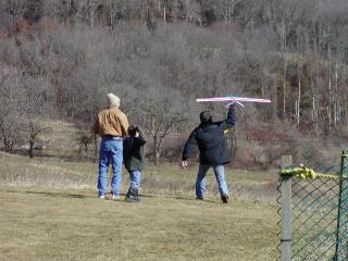
UPDATE: The Polly Wally Flies!!! Maiden voyage was uneventful and beautiful to watch. Theres just something special about watching a bird you have made from scratch take to the air. Many thanks to Dave Baron for his skillful fingers on the sticks .. I was so nervous I probably would have crashed it!! I will update with adjustments and corrections as I continue to dial in Polly. The inverted V-tail seems to work great at 105 degrees but I will be adding a little throw to the controls to add horizontal authority. It looks great in the air.
Additional Note: Paul has informed me that this version as a rudder/elevator plane will not turn well enough. (would need dihedral added) Built as an aileron/elevator plane I feel that the basic layout will lend itself well to being a nice sport plane however. If built with the conversion in mind (ie: elevons end more outboard to allow room for the booms inside them), I see no reason that it couldn't be switched at the field between a Wally Wing and a Polly-Wally very easily. Ken